nRF52 GDB Debugger
Description
The nRF52 GDB Debugger is an inexpensive Open Source blackmagic probe compatible SWD debugger designed to be used with ARM GDB. It supports many platforms, but was primarily designed for use with our Nordic Semiconductor nRF52 BLE boards.
When we built our BlueMicro840 and BlueMacro840 boards, we were looking for an simple option to upload the bootloader without the need to worry about additionnal cables or adapters between the programmer and the board. Then we came across the blackmagic probe (BMP) project - an Open Source debugging tool for embedded microprocessors.
Although the BMP hardware is excellent, it requires the use of adapters to convert the standard 1.27mm 2x5 pins programming header to the larger 2.54mm pin header. So we decided to make use of their liberal open source license and build something that fits our requirements, albeit with less capabilities. To maintain firmware compatibility with the original BMP, we designed it to be compatible with the first version of the BlackMagic probe. As such, the same firmware as the Blackmagic Probe can be uploaded to the nRF52 GDB Debugger.
From a software point of view, using the Blackmagic probe greatly simplifies the debugging and code uploading process by just using ARM GDB - no need to run a GDB server or use an additional complex tool like openocd. Arduino Support for the nRF52 GDB Debugger has been added to the Community nRF52 Board Support Package. This further simplifies the process of uploading the bootloader to the boards.
Final Assembly
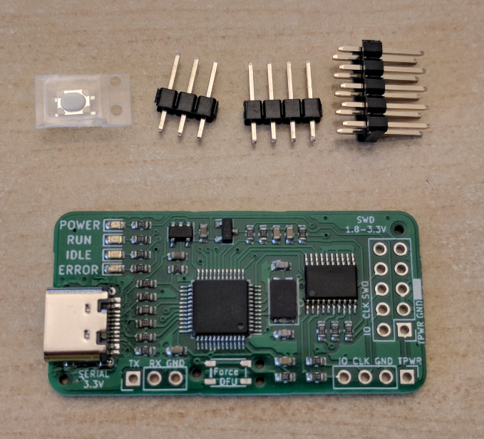
If you purchased an assembled and tested nRF52 GDB Debugger, the USB-C connector will be soldered on. The bootloader and the Black Magic Probe firmware will have been flashed on. To save on potential damage to the headers while shipping, they are not installed on the nRF52 GDB Debugger. You will need to solder these yourself.
- 2x5 Pin header: this is a standard ARM programmer pinout which is designed to be used with the Tag Connect TC2050-IDC-NL programming cable. These are only needed if you plan to use a standard ARM programming cable.
- 1x4 Pin header: this header matches the SWD pins on the edge of the BlueMicro840 and BlueMacro840 controllers. If you only need to flash a BlueMicro840 or BlueMacro840, you only need to install these pins.
- 1x3 Pin header: this header exposes the serial pins of the programmer. These are not generally needed.
- DFU update button: this button is only needed if you need to upload a new version of the firmware to the nRF52 GDB Debugger.
Received a pertially assembled one?
If you purchased a partially assembled nRF52 GDB Debugger, the USB-C connector won't be soldered on. The bootloader will have been flashed but the firmware will not have been flashed.
USB-C Connector
Steps to solder the TYPE-C-31-M-12 from Korean Hroparts Elec onto a PCB using only a Soldering Iron:
- using a no-clean rosin fluxed Solder, pre-apply some solder to the pads, making sure you don't have large "blobs" or joints between pads.
- place the connector on top, making sure to align it properly.
- apply heat to the connector pins. This will solder the pins in place.
- once soldered, move on to the body of the connector, starting with one of the larger pegs.
- Once the 4 metal body pegs are soldered, pass again over the connector pins; making sure that no solder bridges two pins.
Tools I use for soldering the connector:
- TS 100 Soldering Iron with 19V power supply (300C setting)
- TS-D24 Soldering Tip. This is the Chisel Tip one.
- Copper Cleaning Ball for Soldering Iron (ball of copper wool in a metal container)
- MG Chemicals 63/37 No Clean Leaded Solder, 0.032" Diameter
Once you have soldered the connectors on, you will need to test if there are any shorts between VUsb and GND. These are the outermost pins on each side of the connector. Because VUsb is not available on the pins, I use a USB tester. You can test it using a multimeter on the continuity testing function.
Tools I use for testing the connector:
- USB Tester
- 25cm USB-C Cable
- Old phone charger
Flashing the firmware
With the bootloader flashed to the nRF52 GDB Debugger, the LEDs will be cycling/blinking. This indicates that the bootloader is ready to listen to the DFU-Util for flashing a firmware.
You will need to download the latest firmware from the blackmagic github reporitory. Just download the latest .tar.gz file and uncompress it (I use 7-zip). You will need the "blackmagic-native.bin" file from it.
To flash the firmware, you will need the "dfu-util" package. Follow the instructions on Blackmagic's Upgrading Fiwmware wiki page for detailed steps on how to proceed.
Using the nRF52 GDB Debugger to Flash the bootloader to a nRF52
Using the Community nRF52 Add-on Boards in the Arduino IDE, it's possible to unlock and flash the bootloader very easily without the need to configure any special software.
- Select Board type. In this video, it's a BlueMacro840
- If your chip is locked: Select Programmer (use Black Magic Probe - Unlock and Erase)
- Select Serial port from Programmer (there are 2, you may have to try each one)
- Select "Burn Bootloader" while making sure there is good contact with the board. This will unlock the nrf52840 (or nrf52832)
- If your chip is not locked: Select Programmer (use Black Magic Probe)
- Select "Burn Bootloader" while making sure there is good contact with the board. This will flash the bootloader
There are 2 common errors:
- SWD Scan failed: this is generally due to a poor connection with the chip. Note that in the video, I give the BlueMacro840 and nRF52 GDB Debugger a gentle twist to make sure I have a good contact.
- Cannot flash because the chip is protected. You need to "unlock and erase" before flashing the bootloader.
PCB
| Top | Bottom |
|---|---|
 |  |
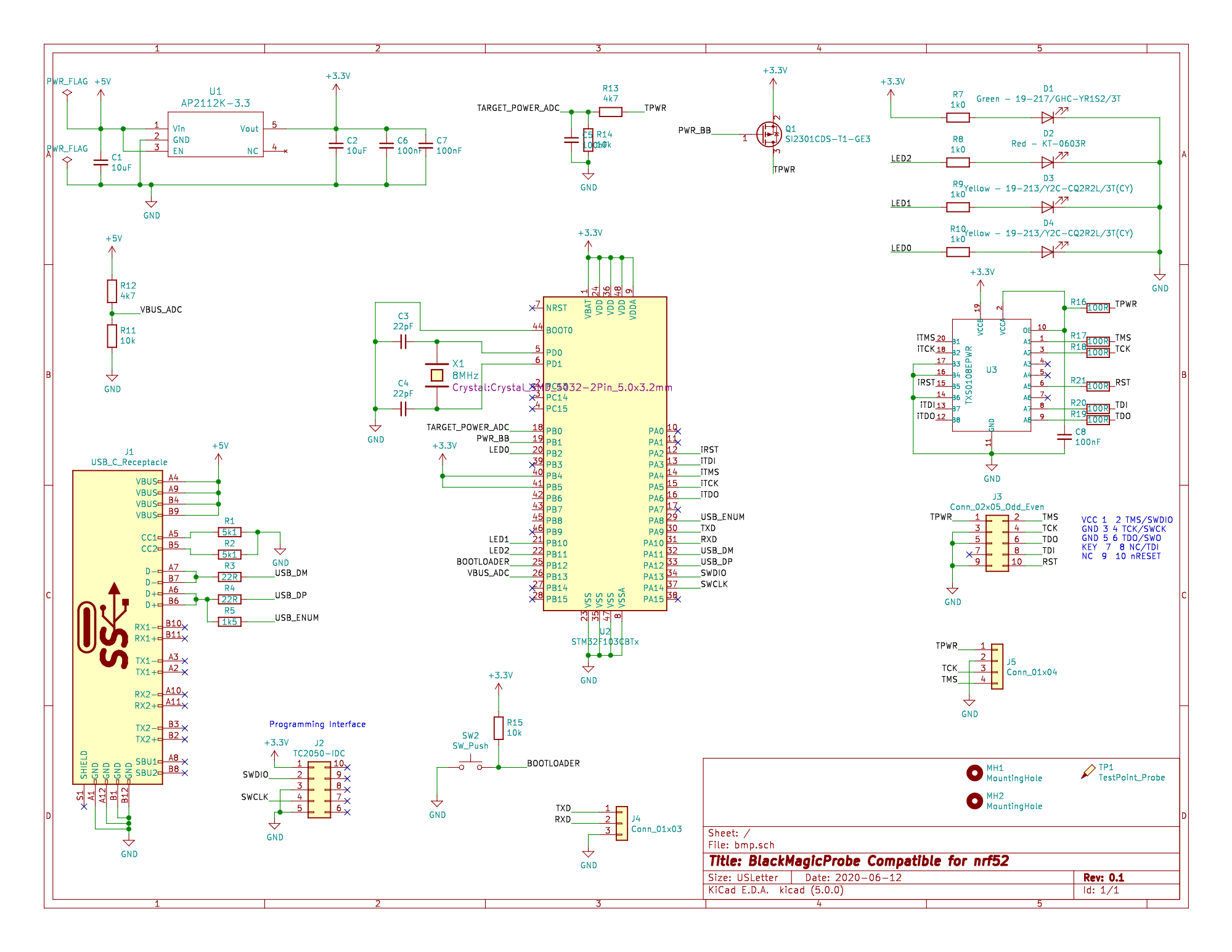
Schematic