BlueMicro840 V1.x
Description
Processor and Module
The BlueMicro840 uses the nRF52840 from Nordic Semiconductors. For an overview of the features of this SoC, refer to Nordic's Product Page. The most important features are as follows:
- 64 MHz Cortex-M4 with FPU
- 1 MB Flash, 256 KB RAM
- 2.4 GHz Transceiver
- -20 to +8 dbm programmable TX Power
- 48 configurable GPIOs
- USB 2.0
For a detailed description of the nRF52840, you can download the datasheet (619 pages).
The BlueMicro840 uses the Ebyte E73-2G4M08S1C module. This module is FCC and CE certified.
The module uses a ceramic antenna and makes 32 GPIOs available externally, 2 of which are reserved for the low frequency crystal oscilator and 1 is reserved for the reset button.
For a detailed description of the module, refer to the manual.
Bootloader
Although the BlueMicro840 can be programmed using the Nordic Software Development Kit and other commercial tools, we recommend using the open source Adafruit nRF52 Bootloader as the bootloader for the BlueMicro840. Two versions of the bootloader are compatible with the BlueMicro840:
- Nordic nRF52840-DK - also named PCA10056
- BlueMicro840.
You can obtain the above bootloaders from the following locations:
- release artifacts of the Adafruit Repo
- release artifacts of the Forked Repo
- Adafruit nRF52 Arduino Board Support Package
- Community Add-on to Adafruit nRF52 Arduino Board Support Package
Firmware
Pinout

NOTE: The Silkscreen on pin 6 (labelled 0.31) is incorrectly printed as 0.31. It should read 0.26. The schematic below is correct.
PCB
| Top | Bottom |
|---|---|
 |  |
NOTE: The Silkscreen on pin 6 (labelled 0.31) is incorrectly printed as 0.31. It should read 0.26. The schematic below is correct.
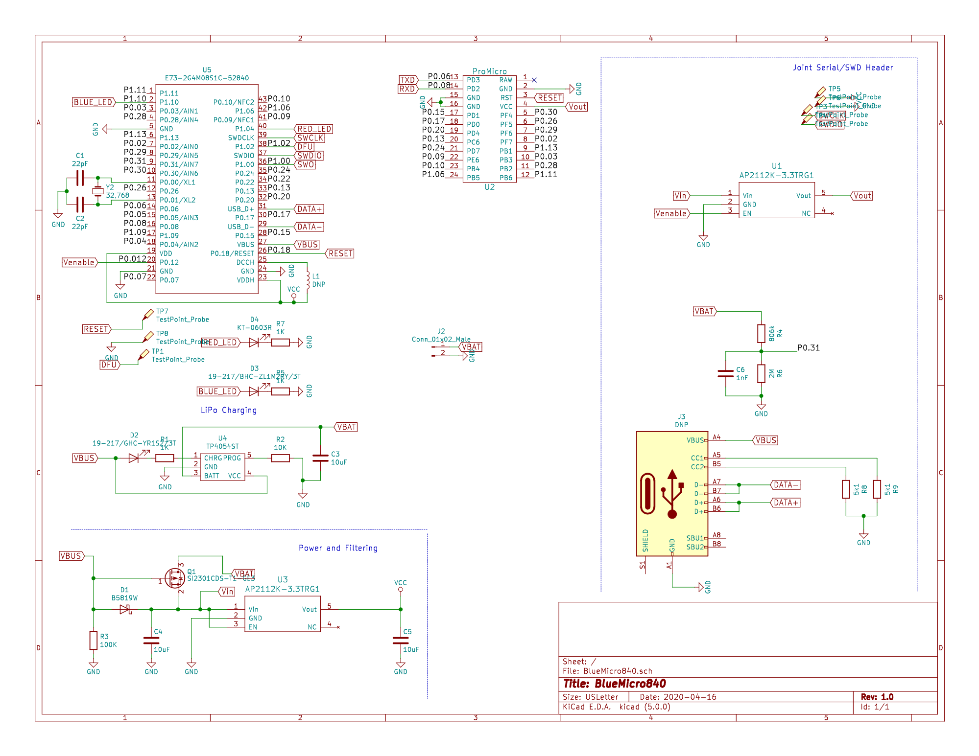
Schematic
Building it yourself?
You need to order the parts included in this csv BOM. You can it load in Excel. The LCSC column refers to the part number at LCSC.com.
Small Components
If you are assembling the BlueMicro840 yourself, refer to the HTML Bom to help you as you assemble it. If you have received the partially assembled boards, you will have all these components already installed and you can move on to the next section.
USB-C Connector
Steps to solder the TYPE-C-31-M-12 from Korean Hroparts Elec onto a PCB using only a Soldering Iron: 1 - using a no-clean rosin fluxed Solder, pre-apply some solder to the pads, making sure you don't have large "blobs" or joints between pads. 2 - place the connector on top, making sure to align it properly. 3 - apply heat to the connector pins. This will solder the pins in place. 4 - once soldered, move on to the body of the connector, starting with one of the larger pegs. 5 - Once the 4 metal body pegs are soldered, pass again over the connector pins; making sure that no solder bridges two pins.
Tools I use for soldering the connector:
- TS 100 Soldering Iron with 19V power supply (300C setting)
- TS-D24 Soldering Tip. This is the Chisel Tip one.
- Copper Cleaning Ball for Soldering Iron (ball of copper wool in a metal container)
- MG Chemicals 63/37 No Clean Leaded Solder, 0.032" Diameter
Once you have soldered the connectors on, you will need to test if there are any shorts between VUsb and GND. These are the outermost pins on each side of the connector. Because VUsb is not available on the pins, I use a USB tester. You can test it using a multimeter on the continuity testing function.
Tools I use for testing the connector:
- USB Tester
- 25cm USB-C Cable
- Old phone charger
E73 Module
With the hidden pads underneath the module, soldering it to a PCB using just a soldering iron isn't a trivial task.
Steps:
- Add a bead of solder to the inner pads of the E73 module. Make sure that they are not too large and are all the same size
- Line-up the beads with the holes matching these pads in the PCB. Since the beads will "fall into" the holes they will "fall in place" somewhat. A binder clip will help hold everything together
- Heat-up the inner pads on the opposite side of the PCB, distributing the heat to all pads so that the solder melt and until there is no gap left between the module and PCB. This will require multiple passes with a larger soldering iron tip to heat more than 1 pad at a time.
- Once the inner pads are soldered, change your tip to a conical one with w relatively fine tip (not super fine). You can then start soldering the outer pads. Make sure to keep the head and iron away from the holes of the PCB. Only heat the castellations of the module, apply a little bit of solder and let it flow towards the PCB pad.
- Go and solder the 3 sides of the module, one joint at a time.
- Once you have all joints done, visually inspect all connections to make sure there are no shorts between pins.
- Go ahead and test with a USB tester. This will make sure there are no shorts in the power circuitry.
- To test the rest, we need to flash a bootloader and some testing firmware on it.
Tools Used:
- TS 100 Soldering Iron with 19V power supply (300C setting)
- TS-D24 Soldering Tip. This is the Chisel Tip one.
- TS-B2 Conical Soldering Tip (not very fine like the TS-I)
- Copper Cleaning Ball for Soldering Iron (ball of copper wool in a metal container)
- MG Chemicals 63/37 No Clean Leaded Solder, 0.032" Diameter
- Small Binder Clip
- Solder Wick
Flash Bootloader
Using the Community nRF52 Add-on Boards in the Arduino IDE and a Black Magic Probe (nRF52 GDB Debugger), it's possible to unlock and flash the bootloader very easily without the need to configure any special software.
- Select Board type. In this case, it's a BlueMacro840
- Select Programmer (use Black Magic Probe - Unlock and Erase)
- Select Serial port from Programmer (there are 2, you may have to try each one)
- Select "Burn Bootloader" while making sure there is good contact with the board. This will unlock the nrf52840 (or nrf52832)
- Select Programmer (use Black Magic Probe)
- Select "Burn Bootloader" while making sure there is good contact with the board. This will flash the bootloader
There are 2 common errors:
- SWD Scan failed: this is generally due to a poor connection with the chip. Note that in the video, I give the BlueMacro840 and programmer a gentle twist to make sure I have a good contact.
- Cannot flash because the chip is protected. You need to "unlock and erase" before flashing the bootloader.
Test USB-C Connector
This step is done after the bootloader is flashed to the chip. With the bootloader enabled, we will see if the computer detects the nRF52840 chip. If the device doesn't connect or if the device is not recognized, it's likely that the data lines on the USB-C connector are not soldered properly.